• Home
  • Register
  • Products
  • Contact us


Home   »   Products   »   Oxy 3 Helicopter Kit

Oxy 3 Helicopter Kit

OXY3-heli

So Sexy, so Superfly

  • Overview

  • Features

  • Models (2)

  • User manual

  • Spare-part

  • Tuning

  • Photos (14)

  • Videos (11)

  • OXY Advisories

  • Media press

  • OXY3 Tutorials

Overview

Oxy Helicopters

The Oxy Helicopter project is a natural evolution for Lynx Helicopters. Experience gained over many years of producing high quality upgrades has placed us in a unique position to enter the helicopter market. Our upgrades have been passionately developed by a core team of engineers and designers, delivering several breakthrough products which improved performance, reliability and maintenance costs of many helicopters. We see the market for small helicopters growing. Flybarless systems have allowed flight characteristics to mimic much larger models, and small brushless motors really pump out the power! It is relatively easy to produce a new helicopter. But much more challenging to design one which can be easily repaired and fly well again after a crash. Here at Oxy, were are not only engineers and designers – we are pilots, and have a clear vision what both 3D pilots and sport pilots require in a helicopter!

The Oxy Helicopter Division

Using the feedback gained from the upgrade market, our unique consolidated design and manufacturing practices, access to the best materials, a huge team of enthusiast supporters and test pilots from all over the world, as well as a powerful distributor network, Lynx Heli has decided to meet market demand for high performance helicopters by forming Oxy Helicopters. We will foster open collaboration with dealers and customers in the community to have the best designs possible.

Our Philosophy: Top Performance and Quality First!

There is a market emerging for high performance helicopters in the 180 to 350mm blade size. Customers don’t want a whole package – they want to pick preferred components like FBL system, blades, motors, servos, ESC, etc. Oxy Helicopters will have top-class, explosive performance, fitting for the best 3D pilots in the world. They will also appeal to sport pilots looking for a high quality, versatile product which is simple to build, maintain and set-up, with clean lines and is crash tolerant. The Oxy Helicopter project is the synthesis of years of ideas. We keep our helicopters simple, robust, light, and of a distinctive style

Our First Helicopter - The Oxy 3

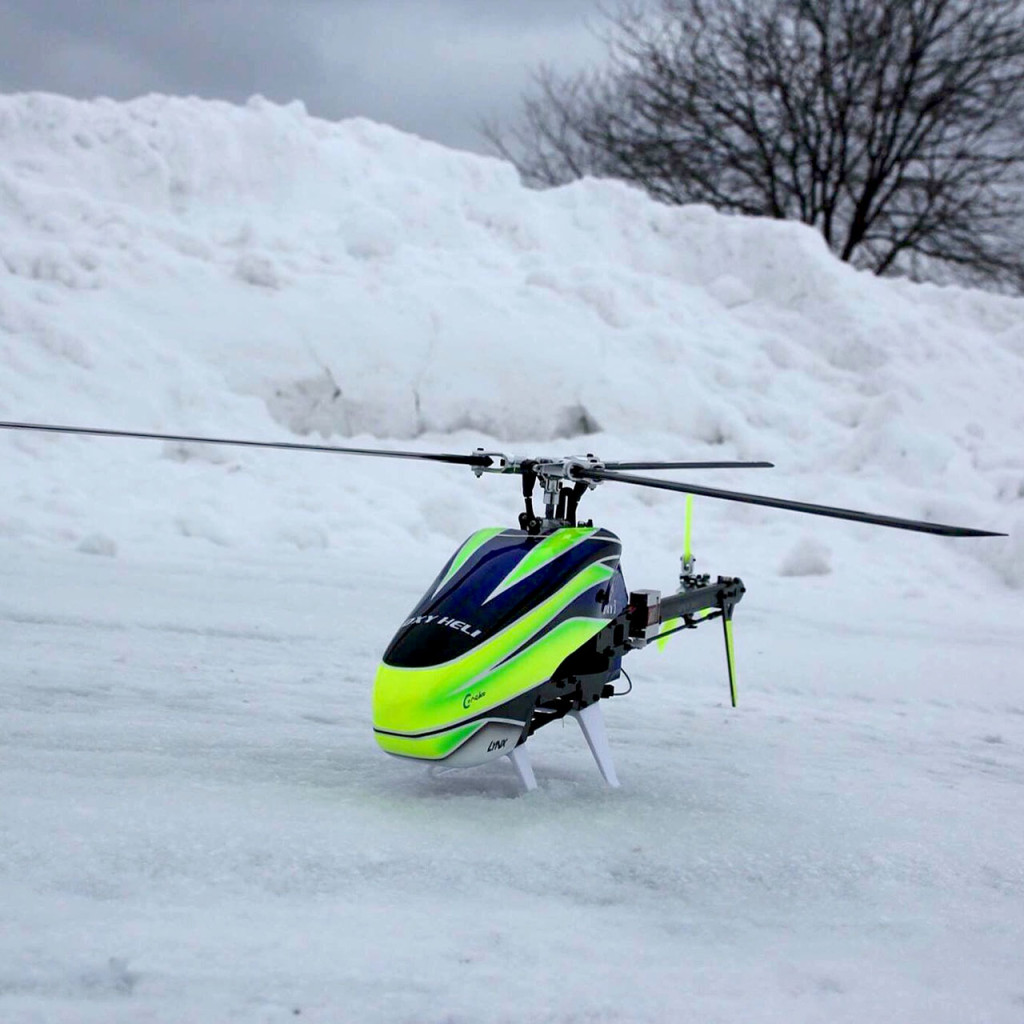
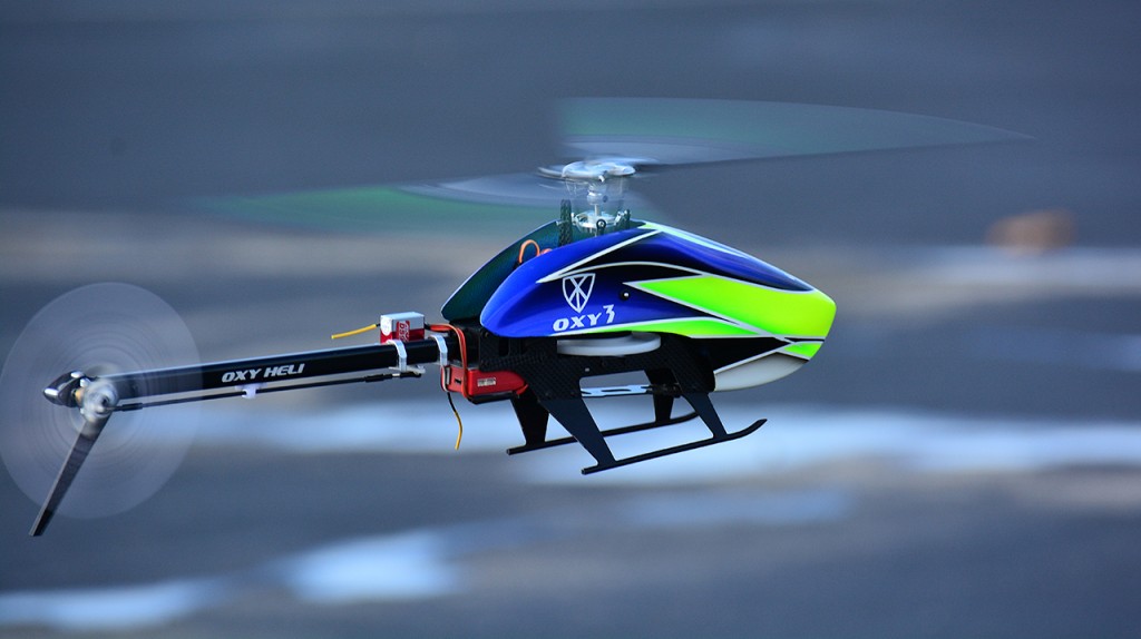
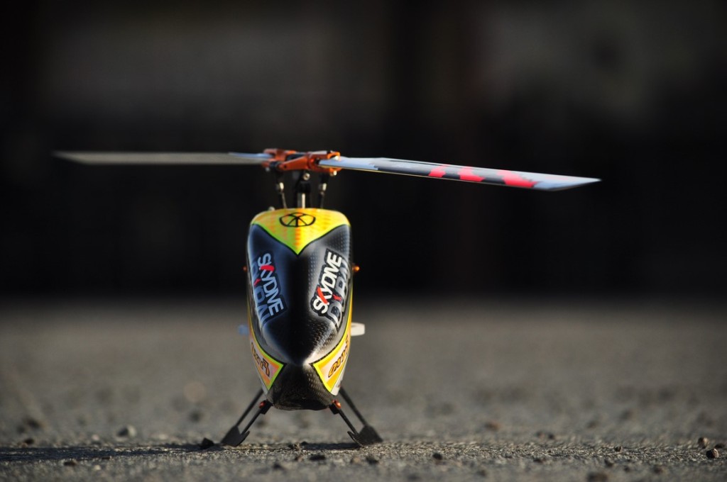
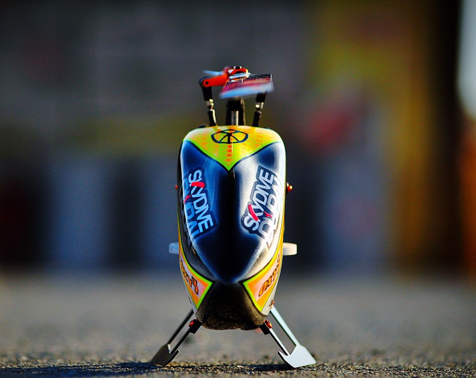
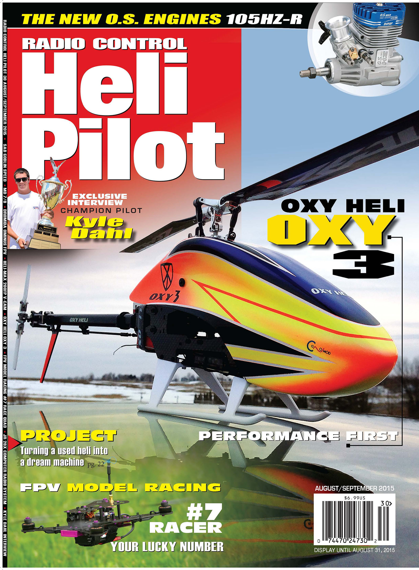
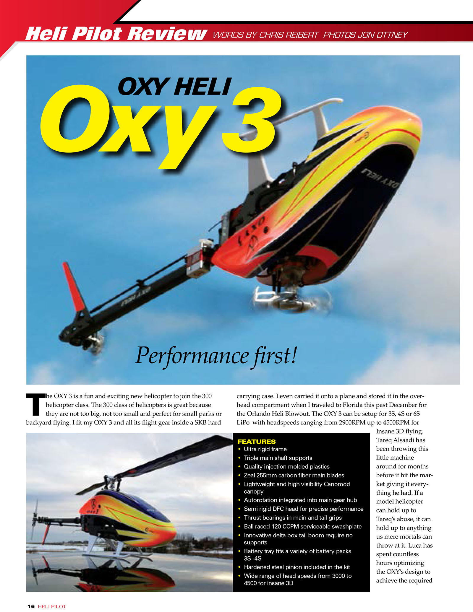
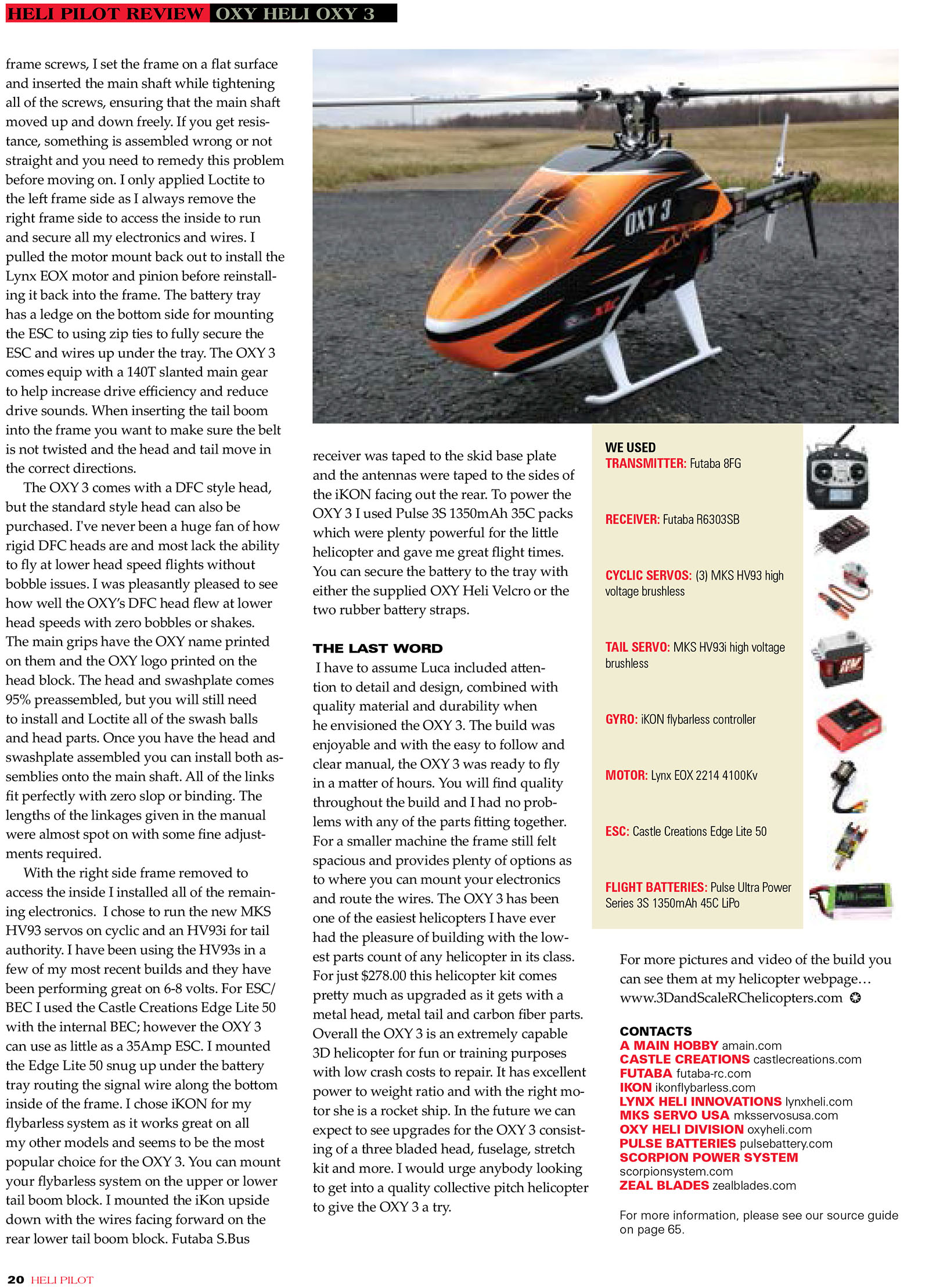
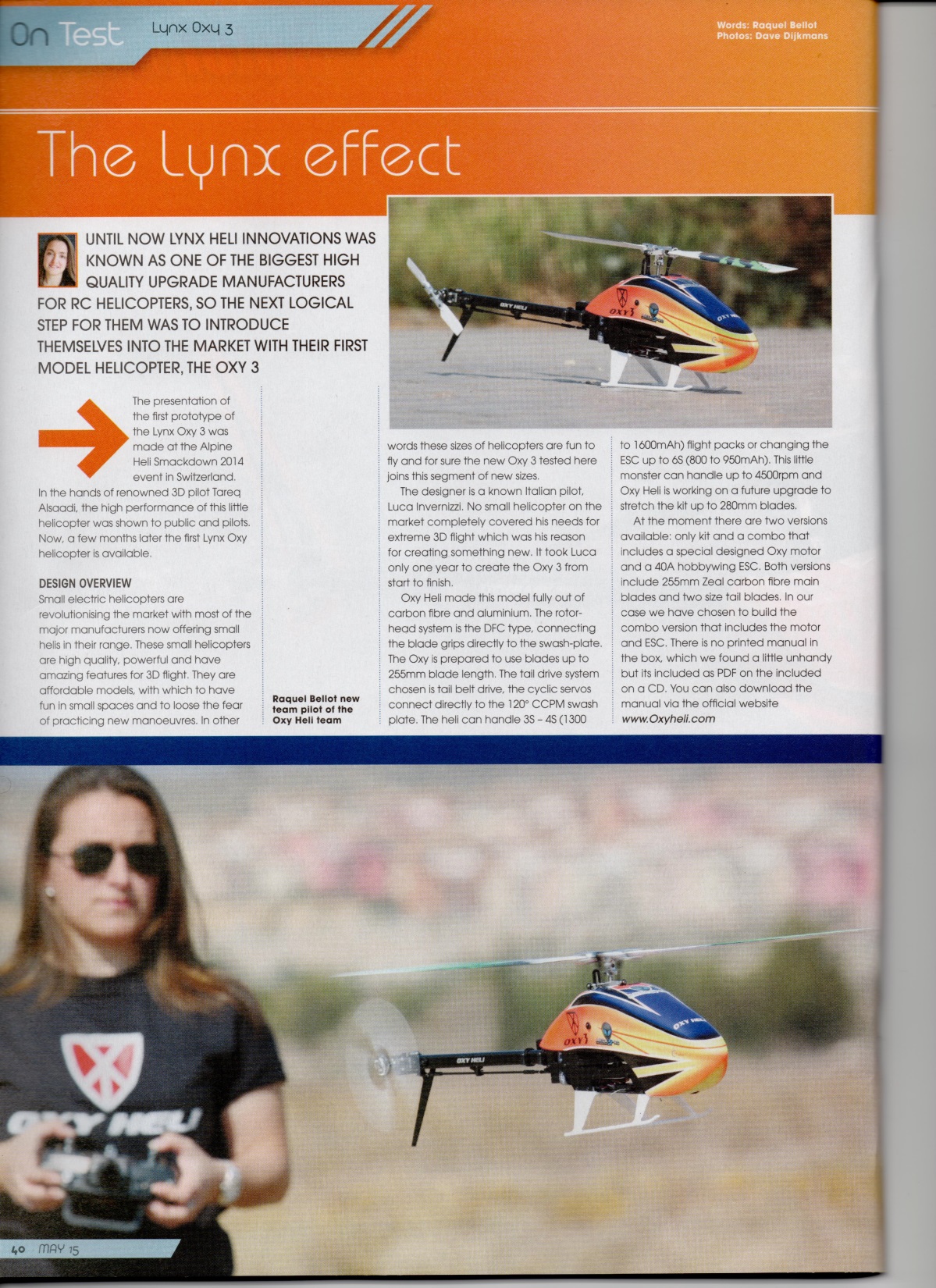
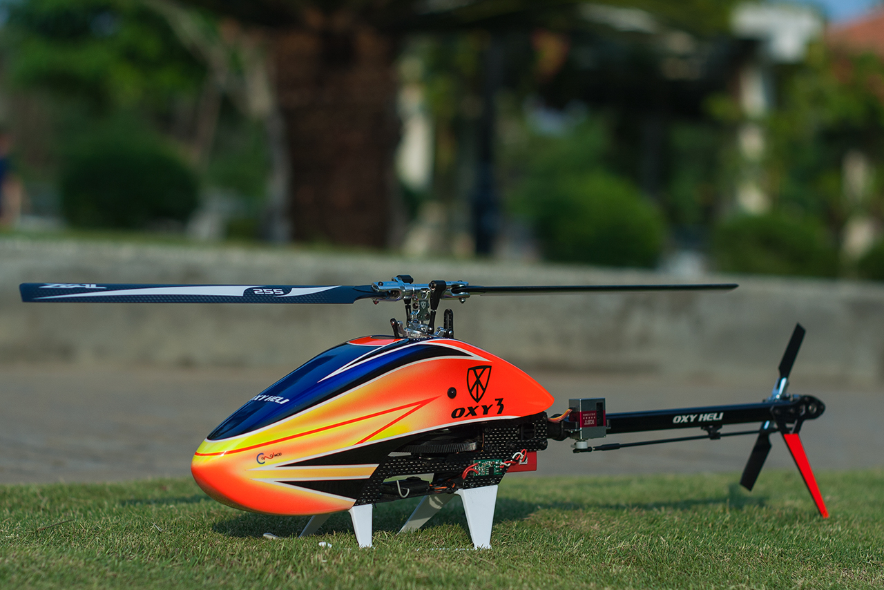
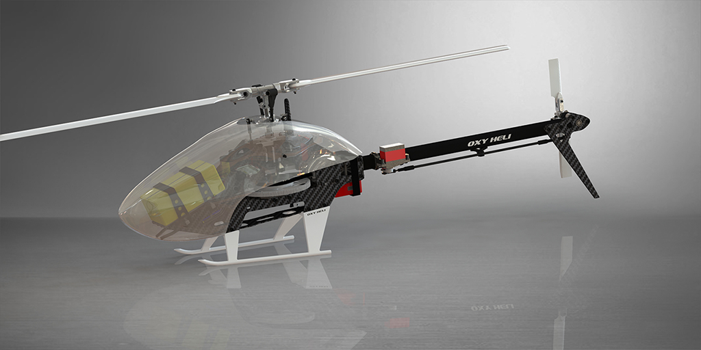
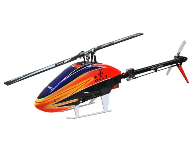
Oxy 3 is the first helicopter in the Oxy Helicopter range. It is a 250 mm blade electric heli, with belt driven tail rotor, suitable for all micro servos. It is designed to handle high rpms (up to 4500), and in the future can grow with a stretch kit up to 280mm blades. Special upgrades will be available to run 3 or 4 blade heads, and a full fuselage to satisfy the requirements of all users
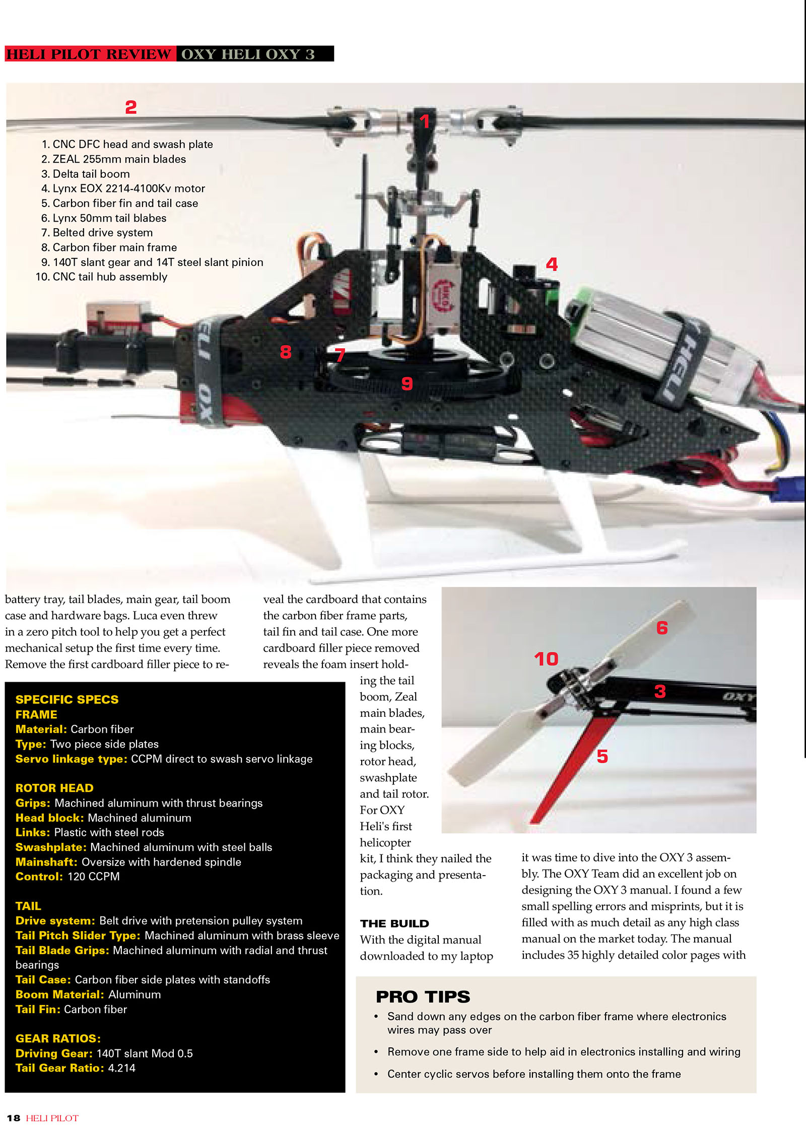
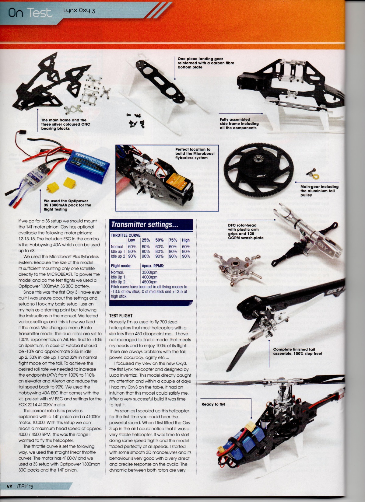
Main features

• Heli designed for intense 3D performance:

- Ultra rigid frame

- Triple main shaft supports

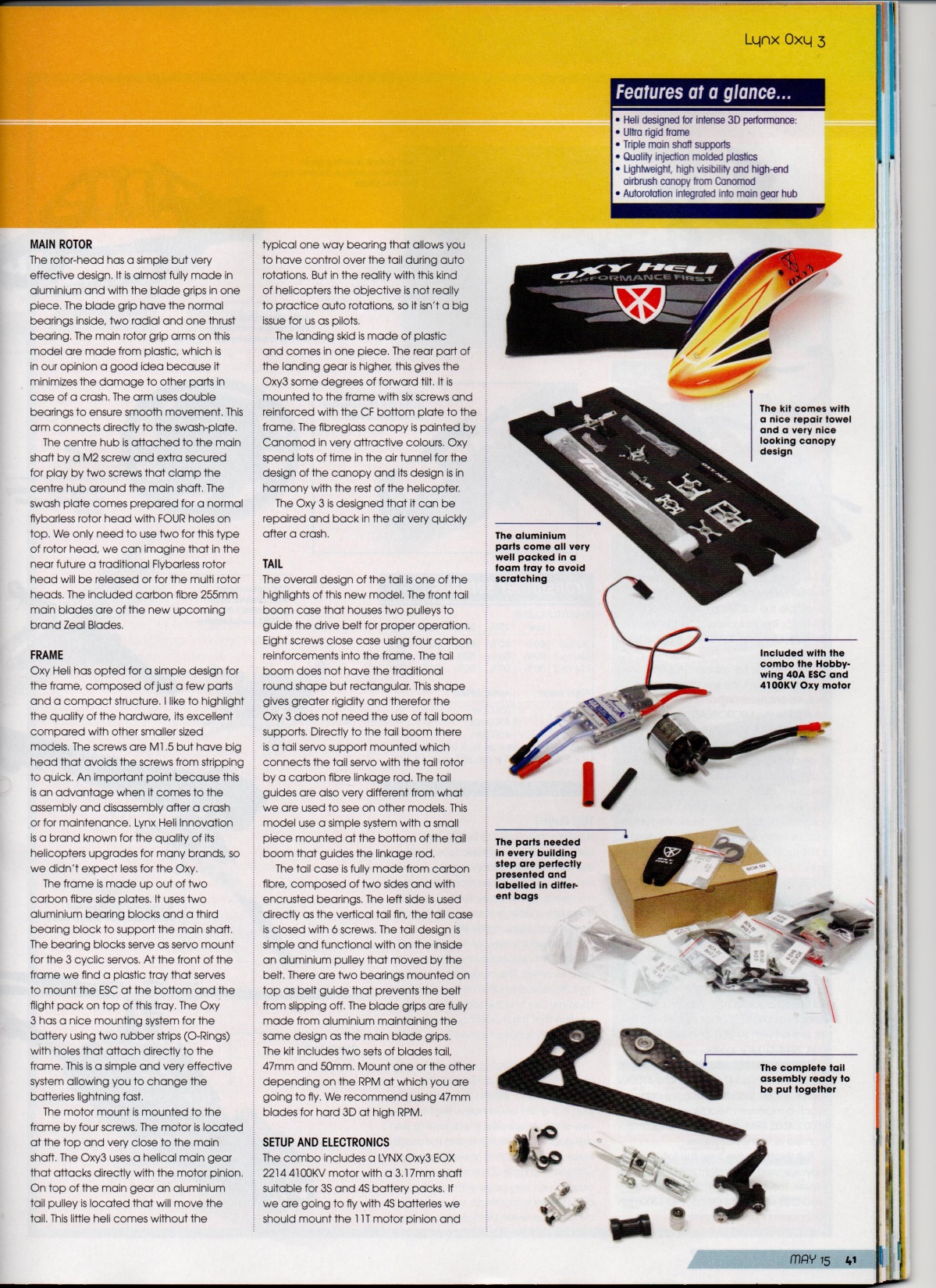
- Quality injection molded plastics

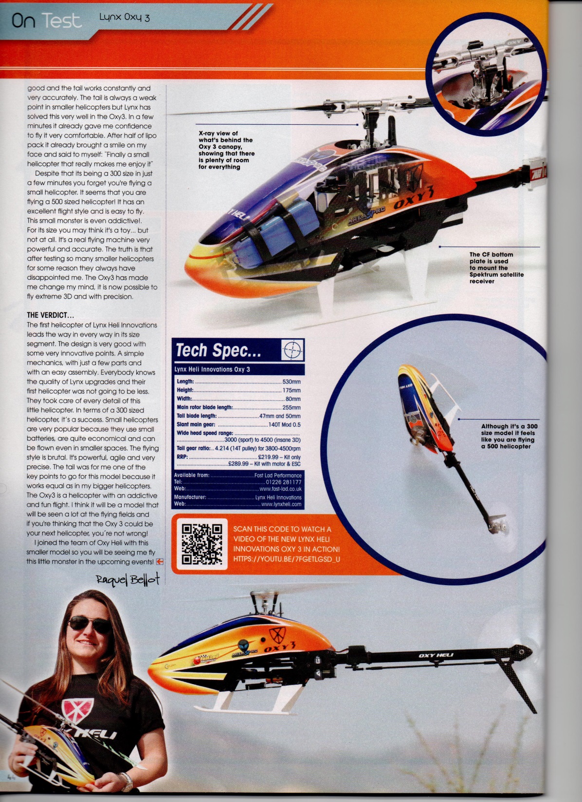
- Lightweight, high visibility and high-end airbrush canopy from Canomod

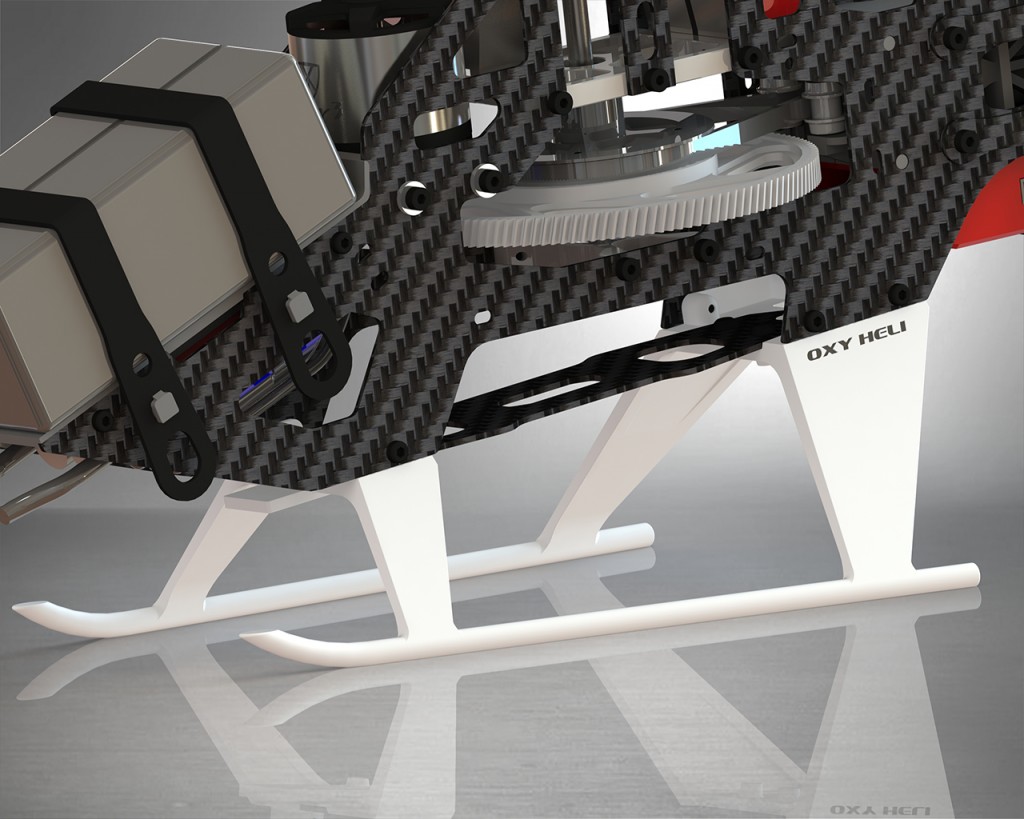
- Autorotation integrated into main gear hub

• Main rotor

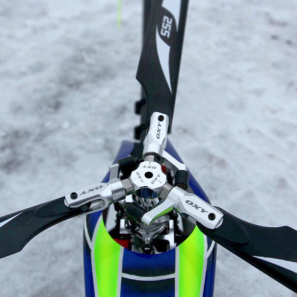
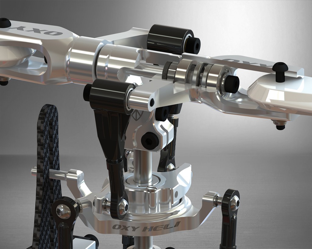
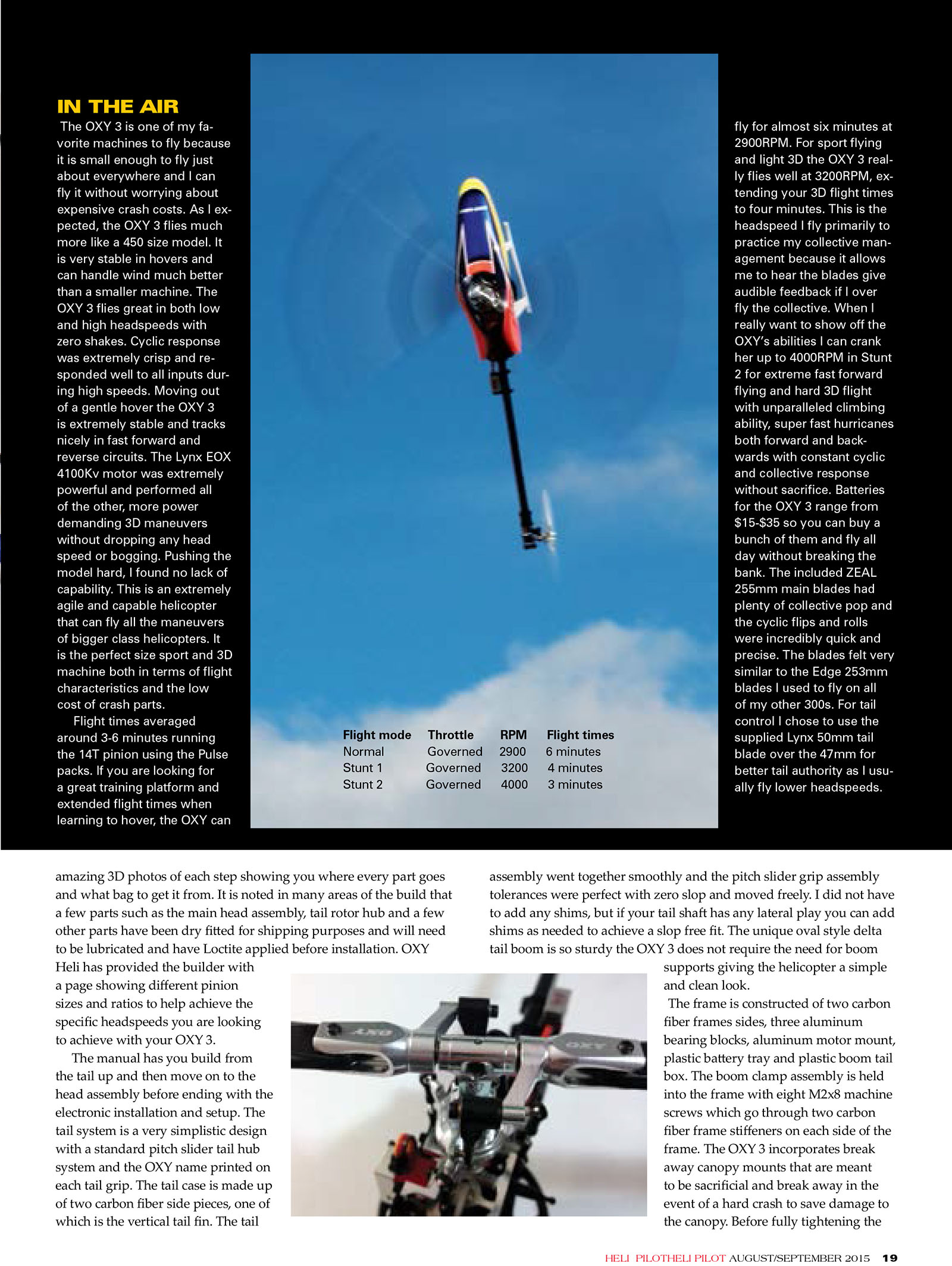
- Semi rigid DFC head for precise performance

- Thrust bearings in main and tail grips

- Oversize hardened spindle

- Ball raced 120° CCPM serviceable swash plate

- Swashplate linkages optimized geometry

• Tail system

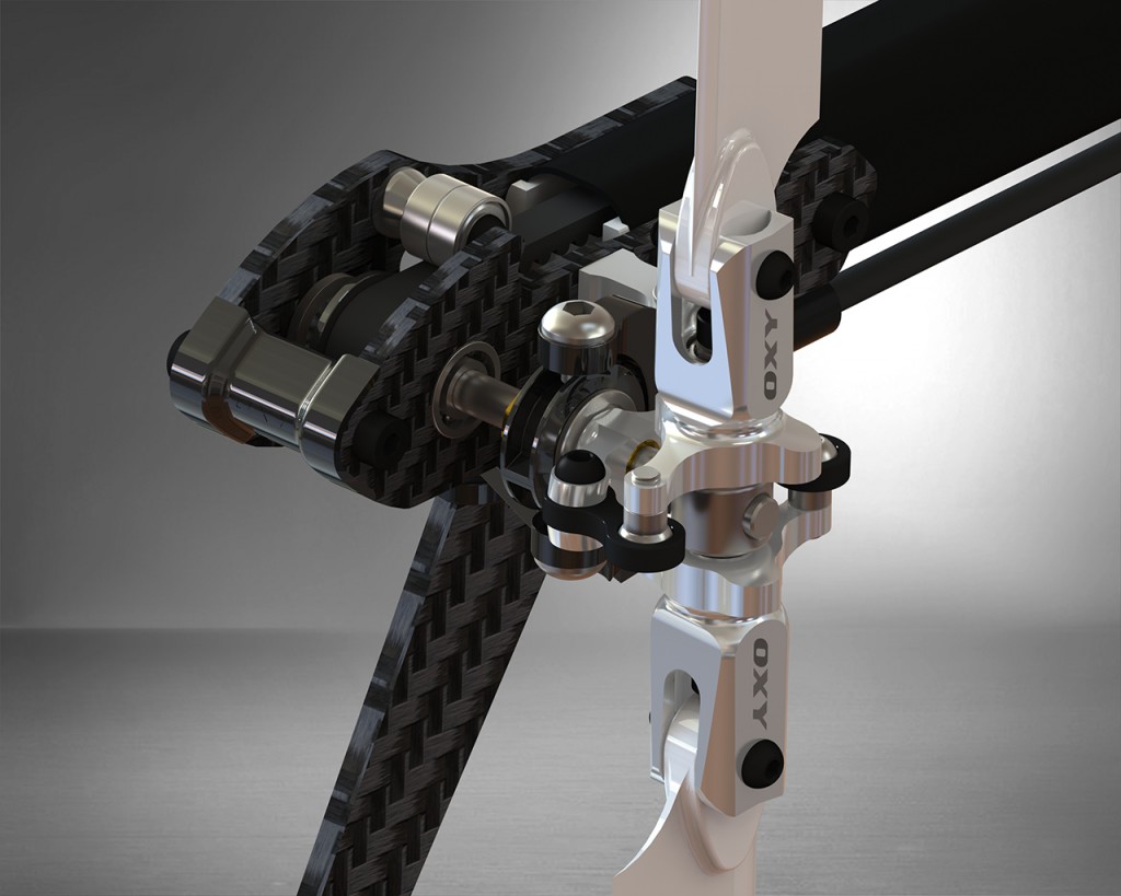
- Belt drive tail (low parts count and low crash cost)

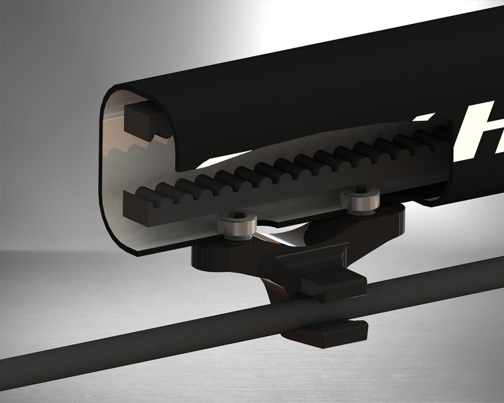
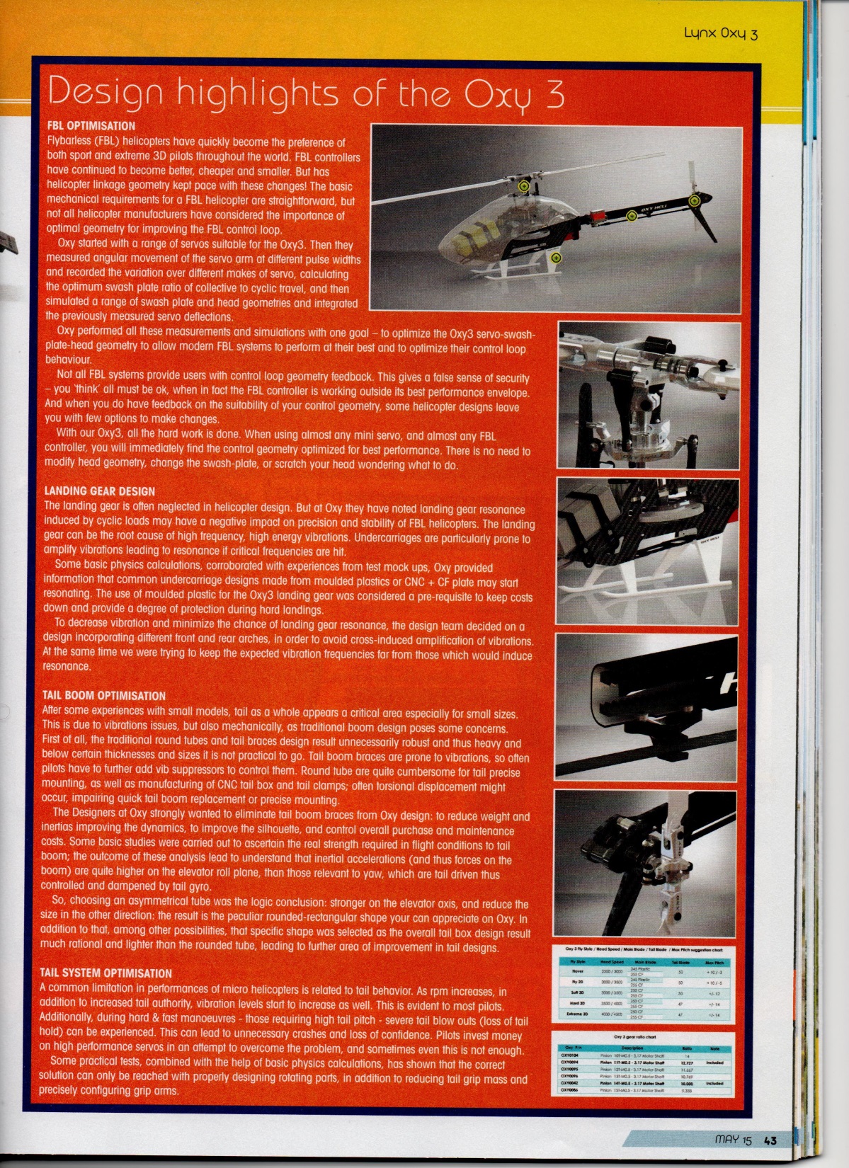
- Innovative delta box tail boom with no requirement for boom supports

- Tail optimized to minimize vibration and servo load at high tail speed

- CNC tail pulley with pretension pulley system

- Rigid carbon fiber 3mm diameter tail push rod for the increased tail control

• Electronics & Power system

- Battery tray fits a variety of battery packs 3s -4s (1300 to 1600 mAh) , 6s  (800 to 950 mAh) –  max length 75mm

- ESC support suitable for 25 – 40A ESC and more

- Kit Motor: EOX 2214 – Black Edition – 4100KV – 3.17mm Shaft – suitable for 3s and 4s battery packs

- Hardened Steel Pinion included in the kit: 11T suitable for 4s – 4100 kV motors and 14T suitable for 3s – 4100 kV motors(optional pinions: 12-13-15)

- Suitable for most micro cyclic and tail servos

- Smart and clean electronic wiring set up

• Specifications

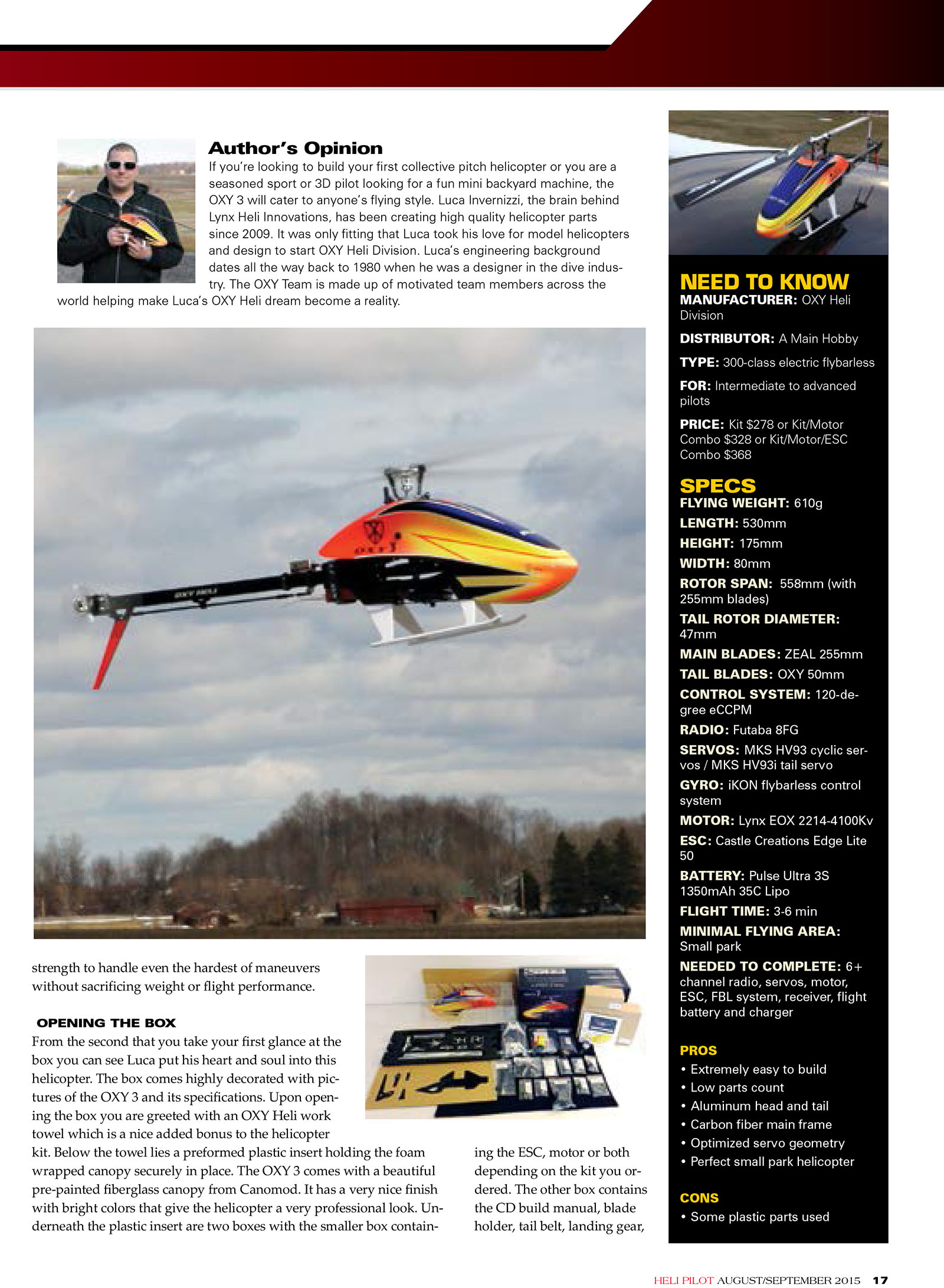
- Length: 530mm Height: 175mm Width: 80mm

- Main rotor blade length: 255mm

- Tail blade length: 47mm and 50mm in std kit for diferent tail autority need (suggested 47mm for Hard 3D Set-Up)

- Slant main gear: 140T 0.5 Mod

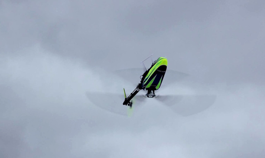
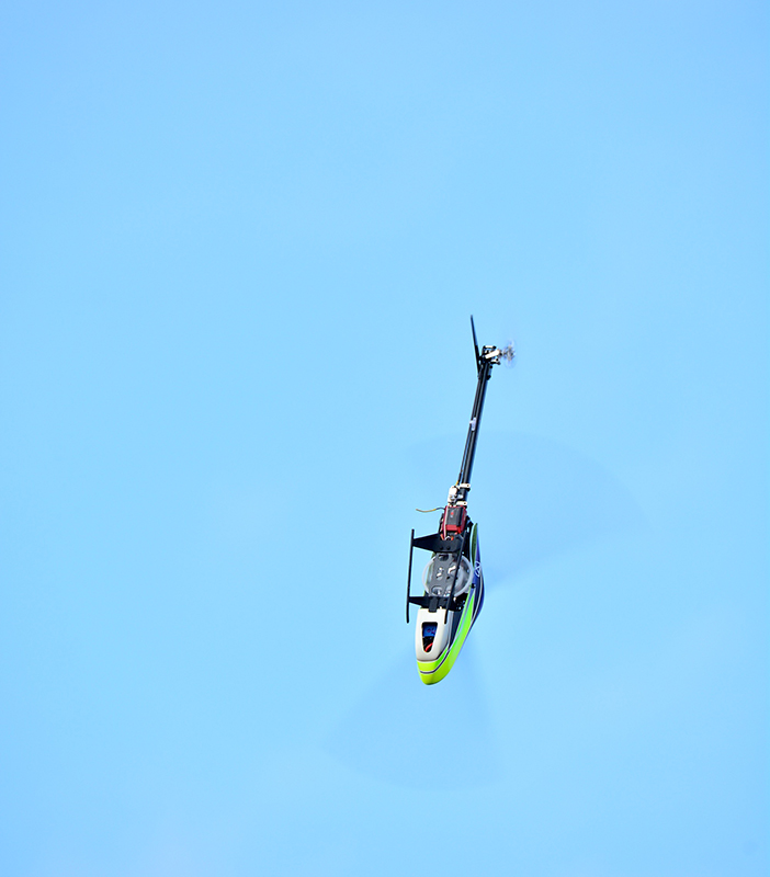
- Wide head speed range: 3000 for sport flying a to 4500 for insane 3D

- Tail gear ratio 4.214 (14T pulley) for 3800 – 4500rpm

- Approximate RTF weight: 580g with 3s 1300mAh battery– suitable for 3.5 minutes of intense 3D at 4000rpm
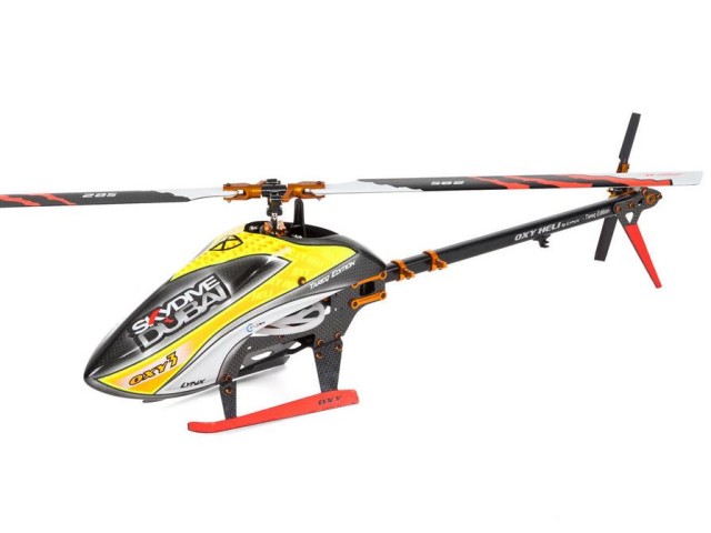
KIT CONTENTS:

  • 1 x Oxy3 Kit
  • 1 x Oxy3 Canopy
  • 1 x ZEAL CF Main Blade 255mm
  • 1 x Plastic Tail Blade 47mm, set
  • 1 x Plastic Tail Blade 50mm, set


Overview

OXY 3 - Canopy design

Canopy

Oxy 3 is a small size heli, but conceived of real high performances: loosing orientation in flight could become a major concern to really exploit its potential. This is why since the origin Oxy 3 canopy had mandatorily to have a large visual footprint in all the directions, combined with “all weather” visible colours and patterning both in forward and reverse flights. Furthermore, canopy is a fundamental element for the protection of heli components, such as electronics, or lipos in case of crash, and a extended canopy helps further.

To maintain a specular aerodynamic performance in all flight conditions , its characteristic shape quite enveloping was selected to cope with the most aggressive tail-is maneuvers helping to obtain a very symmetrical reactions.

A large room for a wide variety of lipo packs , from 3s to 6s, was considered as a mandatory basis for design, resulting in a generous lipo tray, and relevant canopy space on the top of the cockpit.

airframe-1

Similarly, once defined best ESC positioning (for a rational and shortest cable pattern btw lipo and ESC, and Esc to motor, a good airflow to drain easily the most part of dissipated heat), a suitable amount of space was also required on the bottom part of canopy nose, to allocate suitable connectors without crunching cables.

All these constraints resulted in the peculiar canopy shape we all love!

To be honest, canopy was instinctively sketched well before we could realize how many problems that design could have solved, but everything we then would have wanted to solve was actually well covered by the original draft.

OXY 3 - FBL Design

Background

Flybarless (FBL) helicopters have quickly become the preference of both sport and extreme 3D pilots throughout the world. FBL controllers have continued to become better, cheaper and smaller. But has helicopter linkage geometry kept pace with these changes? The basic mechanical requirements for a FBL helicopter are straightforward, but not all helicopter manufacturers have considered the importance of optimal geometry for improving the FBL control loop.

Approach

We started with a range of servos suitable for the Oxy3. We then measured angular movement of the servo arm at different pulse widths, and recorded the variation over different makes of servo. We calculated the optimum swashplate ratio of collective to cyclic travel, and then simulated a range of swashplate and head geometries and integrated our previously measured servo deflections.

OXY-3 Control Geometry

We performed all these measurements and simulations with one goal – to optimize the Oxy3 servo-swashplate-head geometry to allow modern FBL systems to perform at their best and to optimize their control loop behavior. Not all FBL systems provide users with control loop geometry feedback. This gives a false sense of security – you ‘think’ all must be ok, when in fact the FBL controller is working outside its best performance envelope. And when you do have feedback on the suitability of your control geometry, some helicopter designs leave you with few options to make changes. With our Oxy3, all the hard work is done. When using almost any mini servo, and almost any FBL controller, you will immediately find the control geometry optimized for best performance. There is no need to modify head geometry, change the swashplate, or scratch your head wondering what to do. And you will be surprised at the flight performance!
OXY 3 - Landing Gear Design

Background

The landing gear is often neglected in helicopter design. But we have noted landing gear resonance induced by cyclic loads may have a negative impact on precision and stability of FBL helicopters. The landing gear can be the root cause of high frequency, high energy vibrations. Undercarriages are particularly prone to amplify vibrations leading to resonance if critical frequencies are hit.

Approach

Some basic physics calculations, corroborated with experiences from test mock ups, have provided information that common undercarriage designs made from molded plastics or CNC + CF plate may start resonating. The use of molded plastic for the Oxy3 landing gear was considered a pre-requisite to keep costs down and provide a degree of protection during hard landings.

OXY-3 Landing Gear Design

To decrease vibration and minimize the chance of landing gear resonance, the design team decided on a design incorporating different front and rear arches, in order to avoid cross-induced amplification of vibrations. At the same time we were trying to keep the expected vibration frequencies far from those which would induce resonance. In the graph above is a comparison of analytical results of traditional gear design (dotted line), compared with the actual Oxy3 asymmetrical gear design (solid green line), at different frequencies of forcing loads (Cyclic loads induced by the main rotor: 3000-4500rpm, which corresponds to 60-75Hz, and tail vibrations at 18,000-20,000rpm, corresponding to 300-333Hz). We calculated the amplitude of displacement of the skids (vertical axis, in mm: note the logarithmic scale) are compared for both designs, showing the simultaneous benefit of having split the resonance peak in two, and moved towards higher frequencies far from the cyclic load frequencies, and lower than tail induced vibrations. We managed to obtain a significant reduction in global vibrations - to well within an acceptability level. oxy3-landing-gear
OXY 3 - Tail Boom Design

Background

After some experiences with small models, tail as a whole appears a critical area especially for small sizes. This is due to vibrations issues, but also mechanically, as traditional boom design poses some concerns. First of all, the traditional round tubes and tail braces design result unnecessarily robust and thus heavy and below certain thicknesses and sizes it is not practical to go. Tail boom braces are prone to vibrations, so often pilots have to further add vib suppressors to control them. Round tube are quite cumbersome for tail precise mounting, as well as manufacturing of CNC tail box and tail clamps; often torsional displacement might occur, impairing quick tail boom replacement or precise mounting.

The approach

The Designers strongly wanted to eliminate tail boom braces from Oxy design: to reduce weight and inertias improving the dynamics, to improve the silhouette, and control overall purchase and maintenance costs. Some basic studies were carried out to ascertain the real strength required in flight conditions to tail boom; the outcome of these analysis lead to understand that inertial accelerations (and thus forces on the boom) are quite higher on the elevator roll plane, than those relevant to yaw, which are tail driven thus controlled and dampened by tail gyro.

The results

So, choosing an asymmetrical tube was the logic conclusion: stronger on the elevator axis, and reduce the size in the other direction: the result is the peculiar rounded-rectangular shape your can appreciate on Oxy. In addition to that, among other possibilities, that specific shape was selected as the overall tail box design result much rational and lighter than the rounded tube, leading to further area of improvement in tail designs.
OXY 3 - Tail System Design

Background

A common limitation in performances of micro helicopters is related to tail behavior. As rpm increases, in addition to increased tail authority, vibration levels start to increase as well. This is evident to most pilots.

Additionally, during hard & fast maneuvers - those requiring high tail pitch - severe tail blow outs (loss of tail hold) can be experienced. This can lead to unnecessary crashes and loss of confidence. Pilots invest money on high performance servos in an attempt to overcome the problem, and sometimes even this is not enough.

A New Approach

Some practical tests, combined with the help of basic physics calculations, has shown that the correct solution can only be reached with properly designing rotating parts, in addition to reducing tail grip mass and precisely configuring grip arms.

OXY-3 Tail Design

With reference to the above graph, this is an example of advanced tail geometry design optimizations. In this specific case, the effect of proper sizing and positioning of balancing masses (so called Chinese weights) is compared to a conventional tail system (dotted line).

The blue lines represent the torque (kgcm, scale on the left axis) required for the servo to overcome the inertial effects of an unbalanced tail grip (mainly due to the pitch arms), at design tail rotor speed (24,000 rpm). With increasing tail pitch angle we see the inertial counter torque is responsible for apparent servo weakness during fast maneuvers.

The dotted line is the torque required without balancing masses, while the solid blue line is the lowered torque required when using a balanced mass configuration (weight, position and angle).

The green lines represent the unbalanced load (momentum of centrifugal forces, scale on the right axis) acting on the tail grip bearings and hub due to unbalanced tail grip masses (mainly the pitch arms), at design tail rotor speed (24,000 rpm), and for increasing tail pitch angle. These forces are responsible for the vast majority of tail vibrations.

The dotted line is the load without balancing masses, while the solid green line is the lowered load on the tail mechanics resulting from using a balanced mass configuration (mass, position and angle).

As you can see, the results of using appropriate balancing masses improves all aspects of tail behavior.

oxy3-tail-rotor


Overview

Model numberOXY3-255OXY3-Tareq Edition
Oxy 3 Kit DFC Head
Optional FBL Head System Set
Plastic Main Blade 250mm - Orange
Zeal CF Main Blade 255mm
Zeal CF Main Blade 285mm
Zeal CF Main Blade 255mm - Tri-blades
Tail Blade 47mm
Tail Blade 50mm
Tail Blade 47mm - Tri-blades
Pinion 11T
Pinion 14T
Tail Shaft 15T Pulley
Oxy 3 Service Towel
Swash Plate Leveler Tool
Retail Price
$215.00
$285.00
Where to buyWhere to buy

Overview

PDF File
OXY3-255
OXY3-Tareq Edition


Video clips
  • #1 in OXY 3 build series, Introduction to the series.
  • #2 in OXY 3, build series, Tail case.
  • #3 in OXY 3 build series, tail case into the boom.
  • #4 A OXY 3 build series, push rod and support.
  • #4 B, assembling the boom and tail servo mounting.
  • #5 in OXY 3 build series, the frame and it's components.
  • #6 in OXY 3 build series, Motor mounting.
  • #7, OXY 3 build series, installing the boom, main gear and belt. .
  • #8, OXY 3 build series, The head and skids
  • #9 in OXY 3 build series. OXY smooth

Overview

Overview

Overview

Overview

Overview

Overview

  • SP-OXY3-058-8
    OXY3 advisory #1
    15 Mar, 2015

    Our Oxy3 has been selling beyond expectation. We are excited to see so many at local flying fields!
    We have discovered a small issue with some Oxy3 47mm tail blades. Some sets of blades included in our kits were not balanced before leaving the factory.
    Because we wish to support our customers, we will be sending all registered owners a new set of 47mm tail blades, free of charge. These new blades are also further optimized in design.
    Additionally, we have updated the standard tail ratio by changing the stock tail pulley from 14T to 15T. This slightly slows down the tail rotor, which is appropriate if you are running head speeds greater than 4000rpm. We will include this 15T pulley when we send registered pilots the tail blades.
    We advise you to change the tail blades immediately and dispose of the old ones. However, the tail pulley only needs to be changed if you are running high head speeds.

Overview

  • Heli Pilot Aug-Sept 15
    Heli Pilot Aug-Sept 15
    21 Aug, 2015

    Heli Pilot Aug-Sept 15

    Oxy-Heli--SAW---MM---ER-1 Oxy-Heli--SAW---MM---ER-2 Oxy-Heli--SAW---MM---ER-3 Oxy-Heli--SAW---MM---ER-4 Oxy-Heli--SAW---MM---ER-5

  • oxy 3 - oxy heli rotor world article_Page_1
    RotorWolrd 109
    07 Apr, 2015

    oxy 3 - oxy heli rotor world article_Page_1

    oxy 3 - oxy heli rotor world article_Page_2

    oxy 3 - oxy heli rotor world article_Page_3

    oxy 3 - oxy heli rotor world article_Page_4

    oxy 3 - oxy heli rotor world article_Page_5

    oxy 3 - oxy heli rotor world article_Page_6


Overview

  • OXY-3-logo
    How to use the OXY swash tool
    18 Aug, 2016

  • OXY-3-logo
    OXY3 tail shaft play fine tuning
    15 Aug, 2016


Tweet


Copyright (c) 2014 by OXY Helicopter - A Luca Invernizzi Company