


A common limitation in performances of micro helicopters is related to tail behavior. As rpm increases, in addition to increased tail authority, vibration levels start to increase as well. This is evident to most pilots.
Additionally, during hard & fast maneuvers – those requiring high tail pitch – severe tail blow outs (loss of tail hold) can be experienced. This can lead to unnecessary crashes and loss of confidence. Pilots invest money on high performance servos in an attempt to overcome the problem, and sometimes even this is not enough.
Some practical tests, combined with the help of basic physics calculations, has shown that the correct solution can only be reached with properly designing rotating parts, in addition to reducing tail grip mass and precisely configuring grip arms.
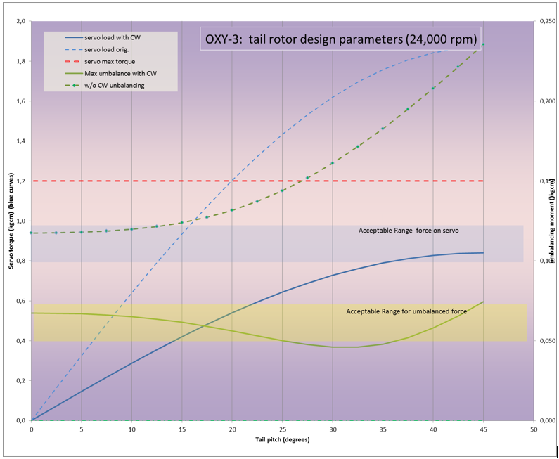
With reference to the above graph, this is an example of advanced tail geometry design optimizations. In this specific case, the effect of proper sizing and positioning of balancing masses (so called Chinese weights) is compared to a conventional tail system (dotted line).
The blue lines represent the torque (kgcm, scale on the left axis) required for the servo to overcome the inertial effects of an unbalanced tail grip (mainly due to the pitch arms), at design tail rotor speed (24,000 rpm). With increasing tail pitch angle we see the inertial counter torque is responsible for apparent servo weakness during fast maneuvers.
The dotted line is the torque required without balancing masses, while the solid blue line is the lowered torque required when using a balanced mass configuration (weight, position and angle).
The green lines represent the unbalanced load (momentum of centrifugal forces, scale on the right axis) acting on the tail grip bearings and hub due to unbalanced tail grip masses (mainly the pitch arms), at design tail rotor speed (24,000 rpm), and for increasing tail pitch angle. These forces are responsible for the vast majority of tail vibrations.
The dotted line is the load without balancing masses, while the solid green line is the lowered load on the tail mechanics resulting from using a balanced mass configuration (mass, position and angle).
As you can see, the results of using appropriate balancing masses improves all aspects of tail behavior.
You must be logged in to post a comment.

